Number of people Enlightened

Wednesday 26 December 2012

BEARING DESIGNATIONS AND MEANING


On board our ships BEARINGS are used in almost every machinery.

But what does a Bearing Mean?

"Bearings are a hardened spherical ball that spins between two surfaces and reduces friction".

We are very well aware of the fact that at the time of ordering or at the time of replacing these bearings there is a Specific number designated to them.  This means that every bearing has been designated with a certain set of numbers and alphabets.  Before getting into the Nomenclature lets take a look at different types of bearings.

Different types of Bearings


  • NEEDLE BEARINGS


NEEDLE BEARING
  • CYLINDRICAL BEARINGS


CYLINDRICAL BEARINGS

  • SLEEVE BEARINGS


SLEEVE BEARINGS

  • SPHERICAL BEARINGS

SPHERICAL BEARINGS


  • LINEAR BEARINGS

LINEAR BEARINGS


  • ROLLER BEARINGS

ROLLER BEARING


  • RADIAL BEARING

RADIAL BEARING


  • PILLOW BLOCK BEARINGS

PILLOW BLOCK BEARING


  • TRACK RUNNER BEARING

TRACK RUNNER BEARING

  • DEEP GROOVE BALL BEARING

DEEP GROOVE BALL BEARING

  • ANGULAR CONTACT BALL BEARING

ANGULAR CONTACT BALL BEARING

  • THRUST BEARING

SELF ALIGNING ROLLER THRUST BEARING
TILTING PAD THRUST BEARING
  • MAGNETIC BEARING


MAGNETIC BEARING
AND THERE ARE MANY OTHER TYPES OF BEARINGS

Now lets find out as to how we can distinguish between so many different types of bearings without even looking at them.

BEARING NOMENCLATURE

Nomenclature depends from manufacturer to manufacturer.  Nomenclature described below is the most common one.

A bearing number has 4 parts to it which includes four numbers and a set of letters.  The first two numbers stand for type and series, the last two numbers designate size and the letters dictate the variation of the bearing.  Lets now take a look at what actually these numbers are and what do they mean:

The first number OR LETTER designates the bearing type.  The first number can be

1 = SELF ALIGNING BALL BEARING
2= SPHERICAL ROLLER BEARING
3= DOUBLE ROW ANGULAR CONTACT BALL BEARING
4= DOUBLE ROW BALL BEARING
5= THRUST BALL BEARING
6= SINGLE ROW DEEP GROOVE BALL BEARING
7= SINGLE ROW ANGULAR CONTACT
8= FELT SEAL ALSO KNOWN AS WIDE CUP BEARING
32= TAPERED ROLLER BEARING
R= INCH NON-METRIC BEARING (i.e bearing dimensions do not comply with metric system)
N= CYLINDRICAL ROLLER BEARING
NN= DOUBLE ROW ROLLER BEARINGS
NA= NEEDLE ROLLER BEARINGS

The second number designates the series or cross section.  It's the ratio of the bore to the width of the bearing, which also controls the OD of the bearing.  The larger the cross section,  the larger the OD of the bearing.  Second number can be

8= EXTRA THIN SECTION
9= VERY THIN SECTION
0= EXTRA LIGHT
1= EXTRA LIGHT THRUST
2= LIGHT
3= MEDIUM
4= HEAVY

The third number is a set of two numbers indicates the bore in mm of the bearings.  All the bearings are designated with metric standards and not inches.  The third number can be

00= 10 mm
01= 12 mm
02= 15 mm
03= 17 mm
For 20-240 mm BEARINGS = LAST 2 DIGITS X 5 = BORE mm
This means if we have the third number as 04 than it would mean that the bore of the bearing is 4x5=20mm or 08 than 8x5=40mm 

The letters indicate the variation.  These vary from manufacturer to manufacturer but the most common ones are as follows

PLAIN= NO SHIELD
TYPE Z= ONE SHIELD (NORMALLY HAVE METAL SHIELDS)
TYPE 2Z= TWO SHIELDS (ONE ON EACH SIDE)
TYPE RS1= ONE SEAL (NORMALLY R INDICATES RUBBER)
TYPE 2RS1= TWO SEAL (RUBBER SEAL ON BOTH SIDES). 
CD= 15 DEGREE CONTACT ANGLE (FOR ANGULAR CONTACT)
ACD= 25 DEGREE CONTACT ANGLE (FOR ANGULAR CONTACT)
V= SINGLE NON CONTACT SEAL
VV= DOUBLE NON CONTACT SEAL
DDU= DOUBLE CONTACT SEALS
N= SNAP RING GROOVE ON OUTER RING
NR= SNAP RING GROOVE ON OUTER RING INCLUDED
M=BRASS CAGE
J= STEEL CAGE
ZBNR= SHIELD AND SNAP RING ON SAME SIDE
ZNJ= SHIELD ON SIDE OPPOSITE SNAP RING GROOVE
ZNRJ= SHIELD ON SIDE OPPOSITE SNAP RING
BLANK= STEEL CAGE

The bearings also have C2, C3, C4 or C5 designation after the bearing number.  This indicates that the internal fit (the inner race to the ball to outer race) is not standard.  Always remember that bearings with these designations need to be replaced with the same designators i.e a C2 bearing is to be replaced with a C2 bearing only.  A C2 bearing is less than standard clearance, while a C3, C4 and C5 are larger than standard.

For further information on bearings and
designations by SKF Click Here 
designations by NSK Click Here or Here
designations by NTN Click Here


Monday 10 December 2012

ENGINE CLASSIFICATION


Engine is something which help us Humans give power which can be used to perform any particular task.  Imagine we cranking an alternator continously to get electricity!!! Instead we the humans made what is a diesel engine which will do this work for us.  I would say that an engine is something which transforms one form of energy to another and as a result make our life simpler and easier.

An Engine can be:

HEAT ENGINE - Engines which converts heat energy into mechanical or electrical energy.  Heat engines are usually Prime movers.

EXTERNAL COMBUSTION ENGINE (EC ENGINE) - Engines in which the combustion of fuel which is directly or in-directly responsible for driving the engine, takes place outside the engine.  Perfect example of this type engine would be steam turbines, where fuel is burnt in a boiler and the steam produced from the boiler is used for driving the Turbine.

INTERNAL COMBUSTION ENGINE (IC ENGINE)  -Engines in which the combustion of fuel takes place within the engine, are called Internal Combustion Engines.  Simplicity in engine design, operational costs and fuel economy is what makes these engines more popular and efficient than EC Engines.

We are more interested in Internal combustion engines as on board motor ships we have this type of engine installed.

Internal Combustion Engines are Classified on the basis of:
  1. IGNITION SYSTEM - Ignition system can be of two types i.e. COMPRESSION IGNITION ENGINES and SPRAK IGNITION ENGINES. 
  • COMPRESSION IGNITION ENGINES (CI ENGINES)- In these types of engines, the heat which is produced due to the compression within a cylinder is so high that it is sufficient enough to cause combustion and as a result there is no other means as such provided to cause the ignition of fuel within the cylinder.  A perfect example of CI Engines is a Diesel Engine.  Figure below illustrates the working cycle of a Diesel engine.  You can also click on this link to get the animated view of the diesel engine.  DESEL ENGINE ANIMATION.  These types of engines are based on DIESEL CYLCLE.


  • SPARK IGNITION ENGINES (SI ENGINES) - In these type of engines, it is the Spark Plug, which produces a spark, causes the ignition of fuel within the cylinder.  This type of engine is found in our Cars and Bikes which we ride in our day to day routine.  Figure below illustrates the working of a Spark Ignition Engine.


Both SI engines and CI engines are internal combustion engines and both make use of liquid fuels.  There are a number of differences between the two.
Table below shows major differences between SI and CI engines.

p.s. Compression Ratio is defined as the ratio of maximum volume of cylinder i.e with piston at BDC (bottom dead centre) to volume of the cylinder with piston at maximum compression i.e with piston at TDC (top dead centre).  Watch this video to understand Compression Ratio.


2. Internal combustion engines can further be classified on the basis of OPERATING CYCLES
 

  • OTTO CYCLE which is also known as CONSTANT VOLUME COMBUSTION CYCLE- It is the standard cycle which is employed in Petrol engines i.e. our car engines.
  • DIESEL CYCLE which is also known as CONSTANT PRESSURE COMBUSTION CYCLE - it is a standard cycle which is employed in slow speed Diesel engines.
  • DUAL COMBUSTION CYCLE which is also known as CONSTANT PRESSURE AND CONSTANT VOLUME COMBUSTION CYCLE - It is a combination of both otto cycle and diesel cycle where heat is partly added at constant volume and partly at constant pressure.  This type of cycle is employed in Medium and High speed diesel engines.
3.  Internal combustion engines can also be classified on the basis of STROKES or CYCLES
Cycles in a engine means the following events:
  • Filling the Engine Cylinder with Fresh Air
  • Compressing the air so much that the fuel vapors which are coming in contact with this compressed air which is now at an elevated temperature due to compression ignites
  • Combustion of fuel
  • Expansion of hot gases
  • Exhaust of these gases after moving the piston
In single word, a cycle comprises  of - INTAKE - COMPRESSION - POWER - EXPANSION - EXHAUST.
Depending on many strokes of a piston are required in completing this cycle, the engines are further divided into 2 classes
  • FOUR STROKE ENGINES -An engine which requires 4 strokes of piston i.e. 2 times up and 2 times down to complete one cycle, is a Four Stroke Engine.
  • TWO STROKE ENGINE - An engine which requires 2 strokes of piston i.e. 1 time up and 1 time down to complete one cycle, is a Two Stroke Engine.
4. Internal combustion engines are also classified on the basis of PISTON ACTION
  • SINGLE ACTING ENGINE - Engines of Single Acting type have one One Piston per cylinder, with the pressure of the combustion gases acting only on the surface of the piston.  Single acting Engines are widely used in Internal combustion engines as well as in many external combustion engines.  This is what we have on Board our ships.


Figure shows a typical Single acting Engine

  •   DOUBLE ACTING ENGINE - In this type of engine both the ends of the cylinder and both faces of the piston are used to develop power i.e. cylinder develops power in both upward and as well downward stroke.


Figure shows a Typical Double Acting Engine
  • OPPOSED PISTON ENGINES - This type of engine comprises of 2 pistons which are traveling in opposite directions.  The combustion space is in the middle of the cylinder and lies between the two pistons.  These engines have 2 crankshafts as well, where the one piston drives one crankshaft and other piston drives the other.  P.S. each piston is single acting.


Figure shows a Typical Opposed Piston Engine

5.  Internal Combustion engines can be classified according to PISTON CONNECTION
  • TRUNK PISTON TYPE - In this type of engine piston is connected directly to the upper end of the connecting rod.  A gudgeon pin or a horizontal pin or wrist pin is what connects the two.  This is the type of engine that we have on board our ships for Medium Speed Engines.


Figure shows a typical Trunk Type Piston
  • CROSS HEAD TYPE ENGINE - In this type of engine piston is attached to a piston rod whose lower end is connected to a Cross head, which slides up and down in guides.  Cross head is connected to the connected rod.  This type of engines are mainly used in large 2 stroke engines and in double acting engines.


Animation shows a typical Cross head Engine
At this point of our learning it would be nice to Compare the two engines i.e.
TRUNK PISTON V/S CROSS HEAD ENGINES

On board our ships most of the Diesel generator make make use of trunk pistons where as the main propulsion engine is crosshead engine.  

CROSSHEAD ENGINE V/S TRUNK ENGINE


KEY - 1-EXHAUST, 2-SCAVENGE AIR RECEIVER, 3-EXHAUST VALVE , 4-CYLINDER HEAD, 5 -A FRAME, 6-CYLINDER LINER, 7-PISTON, 8-SCAVENGING AIR PORTS, 9-PISTON ROD, 10-CROSSHEAD, 11-COLUMN, 12-CONNECTING ROD, 13-CRANKCASE, 14-BEDPLATE, 15-CRANKSHAFT, 16-INLET VALVE


Most of the medium and small size engines use trunk pistons.  As the piston is being pushed upwards by the crankshaft and the connecting rod during compression, resulting side thrust which is produced which causes the piston to press against the cylinder wall, first on one side, then on the other as it moves down.  Thus side thrust alternates from side to side as piston moves up and down.  At the top stroke, when the gas pressure is greatest, side thrust is negligible (this happens in trunk type engines as there is a small connecting rod angle).  So, most of the wear take place at the middle of the stroke: making piston skirt increases thrust bearing area, and hence reduces wear.  In medium and small size engines, due to lower gas pressure, unit's side pressure is so small that neither piston nor liner wears much.

In crosshead engines, crosshead takes the side thrust, which will be high in large engines.  Cross head engines have the following advantages:
  • Easier Lubrication
  • Reduced liner wear
  • Uniformly distributed clearance around piston
  • Simpler piston construction as gudgeon pin and its bearing are note there
On the other hand Cross head engines can have the following disadvantages
  • Greater complication in engine construction
  • Added weight of crosshead
  • Added height due to the addition of another component i.e. Crosshead
  • Need careful adjustments
  6.  Internal combustion engines can also be classified according to CYLINDER ARRANGEMENT
  • CYLINDER - IN - LINE ARRANGEMENT - This is the simplest and the most common arrangement.  In this type of arrangement all cylinders are vertically in line.


Figure shows 4 cylinders in line, however the number of cylinders can go up to 12 but the most common is 6.
  • V-ARRANGEMENT - If an engine has more than 8 cylinders, it becomes difficult to make a sufficiently rigid frame and crankshaft with an inline arrangement.  Also engine becomes quite long and takes up considerable space.  As a result, V-Arrangement is used for engines with more cylinders, (generally 8,12,16) giving about half-length of engine, more rigid and stiff crankshaft, less manufacturing and installing cost.  Angle between 2 cylinders or banks is kept from 30 degree to 120 degrees (most commonly 40 deg, 75 deg)


Figure shows a typical V-Arrangement Engine

  • FLAT ARRANGEMENT -  It is a V-Engine, but this type of V engine has an angle between banks increase to 180 degrees.  This type of engine is mainly used in trucks, buses, rail cars etc.

Animation illustrates a typical Flat Engine
  • RADIAL ARRANGEMENT - In a radial arrangement engine or Radial Engine all the cylinders are set in a circle and all point towards the centre of the circle.  The connecting rods of all pistons work on a single crankpin, which rotates around the centre of the circle. This type of engine was used in aircraft engines but now turbines are more widely used. 


Figure illustrates a typical Radial Engine
7.  Internal Combustion engines can also be classified on the basis of FUEL INJECTION
  • AIR INJECTION ENGINE - The fuel is injected into the cylinder by a blast of compressed air.  This type of engine was heavy and complicated and now is obsolete.
  • AIRLESS (or SOLID or MECHANICAL) INJECTION ENGINE - Fuel is injected into the cylinder, through the fuel valve, by high pressure fuel pump.  At present this is the type of engines which are used.
8.  Internal Combustion engines can be classified on the basis of CHARGING
  • NATURAL ASPIRATED ENGINE - In these types of engines, a vacuum is created as the piston moves away from the combustion and as a result draws in fresh charge.  Our car engine is a perfect example of such type of engine. (petrol engines)
  • SUPERCHARGED ENGINE - In this type of engine charge is admitted into the cylinder at a pressure greater than the atmospheric pressure.  This high pressure can be produced by a pump or blower or Exhaust Gas Turbocharger.  Our ship's make use of Supercharged engines
9.  Internal combustion engines are classified according to FUEL USED
  • HEAVY FUEL OIL ENGINE - These are the engines which can burn high viscosity fuel
  • DIESEL OIL ENGINE - These are the engines which can burn Diesel oil
  • GASOLINE ENGINE - These are the engines which can burn gasoline as fuel.  These engines can also use kerosene.
  • GAS BURNING ENGINE - These are the engines which use gaseous fuels at higher compression.  There are three ways which are adopted to burn these gaseous fuels and as a result these engines are accordingly named.  These engines are:
GAS DIESEL ENGINES - Only air is compressed in these engines.  At the end of compression, gas at high pressure in injected into the cylinder.  With gas, a small amount of fuel termed "pilot fuel" is also admitted into the cylinder to assist in ignition and to cause a smooth and prompt ignition.

DUAL FUEL ENGINE - In these type of engines, gas and air are admitted in the cylinder at the same time and it is the gas/air mixture which is compressed.  At the end of compression, fuel is injected to assist in ignition and cause a smooth and prompt ignition.

Figure shows a typical Wartsila Dual Fuel Engine

HIGH COMPRESSION, SPARK IGNITED GAS ENGINES - In these types of engines, gas and air are admitted in the cylinder at the same time and it is the gas/air mixture which is compressed.  At the end of compression, a spark plug produces a spark which ignites the mixture and causes combustion.

10.  Internal Combustion engines are also classified according Speed
  • SLOW SPEED ENGINES - Engines which have rpm less than 300 r.p.m
  • MEDIUM SPEED ENGINES - Engines which have rpm ranging from 300-1000 r.p.m.
  • HIGH SPEED ENGINES - Engines which have rpm more than 1000 r.p.m.
11.  Internal combustion engines can also be classified according BORE/STROKE RATIO
    Figure shows bore and length of stroke
  • SQUARE ENGINE - If the bore to stroke ratio becomes 1 i.e if the bore is same as stroke the engine is said to be Square Engine.  In this type of engine Crankshaft web dimensions become less compared to journal and crankpin.
  • OVER SQUARE ENGINE (SHORT STROKE ENGINES) - If the bore/stroke ratio is greater than 1, i.e bore diameter is larger than length of stroke.  This allows more valves to be placed in the cylinder head.  These type of engines allow for higher r.p.m and thus more power without excessive piston speed.  These engines have lower friction losses (due to the reduced distance travelled during each engine rotation) and lower crank stress (due to the lower peak piston speed relative to engine speed). Due to the increased piston- and head surface area, the heat loss increases as the bore/stroke-ratio is increased excessively. Because these characteristics favor higher engine speeds, over square engines are often tuned to develop peak torque at a relatively high speed. The reduced stroke length allows for a shorter cylinder and sometimes a shorter connectingrod,generally making over square engines less tall but wider than undersquare engines of similar power.  Source wikipedia

  • UNDER SQUARE ENGINE (LONG STROKE ENGINE) -  If the bore/stroke ratio is less than 1 or if the stroke/bore ratio is greater than 1 then the engine is said to be Under square engine.  This means that the length of stroke is greater than the bore.  At a given engine speed, a longer stroke increases engine friction (since the piston travels a greater distance per stroke) and increases stress on the crankshaft (due to the higher peak piston speed). The smaller bore also reduces the area available for valves in the cylinder head, requiring them to be smaller or fewer in number. Because these factors favor lower engine speeds, under square engines are most often tuned to develop peak torque at relatively low speeds.An under square engine will typically be more compact in the directions perpendicular to piston travel but larger in the direction parallel to piston travel.                                                     Source wikipedia


  • SUPER LONG STROKE ENGINES - To have better propeller efficiency and better combustion even with lower grade of fuels, lower r.p.m. engines with even longer strokes are gaining popularity.  These engines have stroke/bore ration in the range of 3.
At the end of this blog we can now say that there are 11 Different categories of an Internal Combustion Engine.

Tuesday 4 December 2012

FUEL PROPERTIES


      FUEL PROPERTIES

Every engine is run by FUEL. The word "FUEL",in a dictionary would mean "Material such as coal, gas, or oil that is burned to produce heat or power" but in the real world i would define FUEL as "any solid, liquid or gas which has made a superabundant impact on the world's economy or in other words it is the driver of world's economy and is the prime driving source for every mode of transportation, production, communications, etc". In simple terms FUEL runs the world we live in or we can't live without fuel.

Now as Marine professionals what impact has fuel made on us?
Well the answer is simple.

Fuels run our ship i.e. fuel is the prime source for our ship's propulsion and electricity. Without fuel on board, ship is a Dead ship.

So what's all the fuss with fuel?

Unlike water as discussed in section "BOILER WATER", fuel too is full of impurities.

Before we proceed further it is important for us to know where we get our ship's fuel. To understand this let's go Back to School.


BACK TO SCHOOL
Formation of fuel is like a fairy tale which started millions and millions of years ago, where there lived tiny marine organisms who died and decomposed in the bottom of the ocean to form oil and natural gas, which drives our world today. A simple pictorial representation below will explain the entire process of formation of oil and natural and natural gas.


Now that we know from where this oil or crude oil is coming from, let's find out how and where our Marine Fuels come from.
Once this Crude oil is extracted from the under the earth, it is transported to a Refinery where it is subjected to the "REFINING PROCESS".

 Lets now again have a look at a simple Refining process picture which explains it all.


                                                                                                                                        Source: eetindia    

A brief description of how Refining Process works.
Refining process is a compilation of following methods:

  • CRACKING - Breaking large hydrocarbons into smaller pieces which in turn is of 2 types i.e THERMAL and CATALYTIC 
  • UNIFICATION (Done by a process called CATALYTIC REFORMING) - Combining smaller pieces to larger ones 
  • ALTERATION (Done by a process called ALKYLATION) - Rearranging various pieces to form desired hydrocarbons 
Now that we have understood the Refining Process, lets now take a look at the types of Marine Fuel used on board ships.


CLASSIFICATION OF FUEL FOR MARITIME USE

  • HFO or MFO (HEAVY FUEL OIL) or (MARINE FUEL OIL) - This type of fuel is purely Residual oil. 
  • IFO (INTERMEDIATE FUEL OIL) - A blend of Heavy fuel oil and gas oil, with more of marine diesel oil and less of gas oil. IFO380 or IFO180 fuels are generally used on board ships. 380 and 180 represents the fuel viscosity. Another type of fuel which now recently has gained a lot of importance in the maritime industry is LS380 or LS180 which is Low Sulphur fuel. 
  • MDO (MARINE DIESEL OIL) - A blend of heavy Diesel oil which may contain small amounts of black refinery products, but has a low viscosity and as a result does not require heating and can be used in internal combustion engines 
  • MGO (MARINE GAS OIL) - is pure gas oil made from distillate only 

Fuel properties define engine's performance, reliability, efficiency, life, and TBOs (Time between Overhauls) and fuel properties at the same time illustrate the engines impact on environment.

Lets try to understand the concept this way,
To run an engine we need to burn fuel. When we burn fuel,certain ash formation and smoke is inevitable. Now that we are burning residual fuels, formation of deposits, harmful smoke is quite natural. At this point, am sure your mind will pop with this question "Why is maritime industry not making use of fuels which are formed higher in the refinery process?" 
The answer is simple. Residual fuels are very cheap compared to other distillate fuels. Also if Residual fuels were to be used in our cars, we could expect them to be very heavy and quite huge as to burn and use HFO, as fuel requires a heating plant.


So who defines the minimum standards for fuel which can be used on board?
As residual fuels are quite full of impurities, refining them to a certain level is very important, so that they give a good combustion effect and at the same time minimise effects on the enviornment. Now all this is pre- defined and regulated. Fuel on board needs to have a certain minimum specification and ISO governs these standards.

What is ISO?

ISO is International organization for standardization and is the world's largest developer of voluntary International standards. These standards help give state of the art specifications for products, services and good practice, and this helps make any industry more efficient and effective.

For any further information about ISO you can visit their website ISO .


Now that we know what ISO lets take a look at which particular section of ISO deals with marine fuels.

ISO has developed over 19000 international standards and all these standards are included in the ISO Standards Catalogue. There are three ways to find our standard i.e Standard on Marine fuels

  1. Browsing by International Classification for standards (ICS)
  2. Browsing by Technical committees (TC)
  3. Search the standards catalogue using the number of standard i.e. all ISO standards are numbered 

Finally, our standard for Marine Fuel is found. It's ISO 8217, where the number 8217 simply states the standard number in the standards catalogue.

Apart from fuel specifications, there are many ISO standards which outline minimum standards which must be adopted at the time of fuel testing.

Below table illustrates the fuel properties & test methods as outlined in the various ISO standards. (This table is what describes Fuel Analysis report)

Table below is for Fuel Oil.


                                                                                                                                        Source - Chevron


Table below is for Diesel Oil


                                                                                                                                        Source - Chevron


All other parameters seem quite familier but what's with these abbrevations RMA, RMD, RME, RMB, DMX, DMA, DMZ, DMB etc?
Like MAN B&W engine designations we have Fuel designations which tell us a lot about the fuel.
Category of fuel consists of these three letters
  1. The first letter of this category is always the family letter which is "D" or "R".  "D" is for Distillate and "R" is for Residual
  2. The second letter, "M" is for the application which is Marine
  3. The third letter X,A,B,C,....K, indicates a particular property as specified in the product specification of ISO8217
Let's now take a look at fuel properties one by as mentioned in the fuel report and its impact on engine:

  • VISCOSITY -  The recommended viscosity range at engine inlet is 13-17 cSt (mm2/s).  The preheating temperature can be estimated from the approximate viscosity vs. temperature chart which can be found in Instructions manual.  For a standard 380 cSt fuel (at 50 deg c), the fuel must be preheated to about 130 deg c.  Viscosity cannot be considered a quality criterion and is stated only for handling purposes i.e. how would pumps, preheaters and centrifuges behave.
  • Density at 15 deg c - Density is related to fuel quality.  As stated above, we have seen that fuels are derived from extensive refinery process which imparts large amounts of carbon content, fuels become more aromatic and thus heavier.  This means that fuels with higher density are high in carbon residue and asphaltenes.  Density is normally measured at higher temperatures, and the density at 15 deg c is calculated on the basis of tables which, depending on their origin, date of issue, and the data on which they are based.   
The next question which might crop in your mind now is what's with this 15 deg c?  Answer is simple, value stated for density is at 15 deg c.  Now you may wonder why 15 deg c, why not 20 deg c?  Answer to this would be it was AMERICAN PETROLEUM INSTITUTE(API) long time back, which had set a standard for measuring density at 60 degree fahrenheit or 15.6 degree celsius.  So next time if surveyor asks you why its 15 degrees you know the answer.
Density also governs the water separation ability of the fuel i.e. we adjust gravity disks on purifiers as per density. 
  • CCAI (CALCULATED CARBON CONTENT AROMATICITY INDEX) and CETANE INDEX - Gives a value on Ignition quality of residual fuels.  CCAI gives us an idea about how much is the ignition delayed during a combustion process i.e. greater the CCAI index, longer will be the ignition delay.  During the combustion process there is a delay i.e. once the fuel is injected in the cylinder it takes a while to get ignited . (This topic will be dealt with in details under section INDICATOR DIAGRAMS later only on nalinbaijal.blogspot.com)  This delay however is controlled, but if the delay prolongs then a large amount of fuel is injected before the combustion starts, producing a quick and a violent raise of pressure.  This produces what is called "DIESEL KNOCK".  CCAI is calculated from density and viscosity of the fuel.       
CETANE INDEX - Cetane Index acts as a substitute to Cetane number for diesel fuel.  Cetane number is a measure of diesel fuel ignition delay which can also be defined as the period between the start of injection of fuel in the cylinder and the first identifiable pressure increase during combustion of the fuel.  Higher the Cetane number, lesser is the ignition delay and lower the Cetane number higher is the ignition delay.

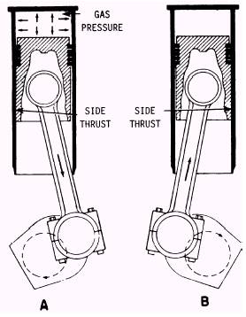
It is important that engine is run within specified CCAI or CI limits or other wise stresses on engine components might increase considerably and special attention needs to be paid to the following engine components:
  1. Connecting rod big-end bearing shells
  2. Piston, piston rings and liners
  3. Main bearing shells
  4. Cylinder head with studs and gaskets
  5. Tie Bolts
  6. Intake and Exhaust valves
To mitigate the effects of ignition delay or out of specification CCAI and CI, following steps are to be taken
  1. Keep the engine load within 50-85%
  2. Maintain inlet air temperature as high as possible
  3. Lubricating oil must be in excellent working condition as there is a possibility of compromising oil's property due to blow by (higher combustion pressures)
  • SULPHUR - Sulphur content of fuel oil or diesel oil has zero impact on combustion process, but still it is one of the most important parameters in the above table. 
Before we proceed further at this point it becomes important for us to understand the meaning of the term SOX.  
SOX is used to indicate the general oxides of Sulphur (SO2, SO3, etc). 
In diesel engines, fuel is injected in cylinder in which air is at very high pressure due to compression by moving piston. This compression raises the temperature of the air sufficiently to cause the fuel to ignite. Combustion proceeds around the periphery of the fuel spray at temperatures around 2000°C.
Oxides of sulphur are formed during the combustion process, by combination of the sulphur in the fuel with oxygen. The prime constituent of SOx is SO2. The amount of SOx formed in an engine depends primarily on the concentration of sulphur in the fuel. SOx emissions from ship engines are relatively high because they burn high sulphur content fuels. This Sulphur dioxide then rises into the atmosphere and is oxidized once again in the presence of atmospheric hydroxyl radicals to form sulphur trioxide (SO3). Sulphur trioxide reacts with atmospheric water droplets or vapors to form sulphuric acid (H2SO4) and eventually results in Acid Rain.
Recently many engine modifications and numerous law modifications were made and are still being formulated to help prevent our environment and protect human lives from impact of emissions.
Sulphuric acid can also be formed during combustion and its effects are counteracted by adequate lube oils and temperature control of the combustion chamber walls.

What does IMO say about sulphur?

In 2008 the revised Annex VI to Marpol 73/78 was adopted and required the sulphur content of any fuel used on board ships not to exceed :
• 4.50% m/m prior to 1 January 2012
• 3.50% m/m on and after 1 January 2012
• 0.50% m/m on and after 1 January 2020 or 2025,
depending the outcome of a review to be completed by 2018 to determine availability of fuel oil to comply
with the fuel oil standard. Additionally, the revised Annex VI to Marpol 73/78 restricts the sulphur content of fuel oil used on board ships operating within an Emission Control Area (ECA) to :
• 1.00% m/m on and after 1 July 2010
• 0.10% m/m on and after 1 January 2015.
Annex VI to Marpol 73/78 allows for alternative technologies/methods which are at least as effective in terms of emissions reductions. Currently adopted ECA areas are the Baltic Sea, North Sea and English Channel, the U.S. Caribbean ECA (including designated waters adjacent to Puerto Rico and the US Virgin Islands) and the North American ECA (including waters adjacent to the Pacific Coast, the Atlantic/Gulf Coast and the eight main Hawaiian Islands, extending up to 200 nautical miles from coasts of the United States, Canada and the French territories). In addition, the EU directive 2005/33/EC extended the           1.5 m/m % S limit to ferries operating to and from any EU port.
The EU directive also has set a maximum limit of 0.1 m/m % on the sulphur content of marine fuels used by ships when at berth for more than 2 hours. The process to review the EU Directive 2005/33/EC started in 2011. Therefore, the limits and requirements stated above are subject to change. In California, the Ocean Going Vessels (OGV) Clean Fuel regulation applies to OGV main diesel engines, auxiliary diesel engines and auxiliary boilers, and requires:
1) the use of marine diesel DMB:
— at or below 0.5 m/m % sulphur
— at or below 0.1 m/m % sulphur as of January 1, 2014; or
2) the use of marine gasoil (DMA/DMZ):
— at or below 1.5 m/m% sulphur prior August 1, 2012
— at or below 1.0 m/m% sulphur on and after August 1, 2012
— at or below 0.1 m/m% sulphur on and after January 1, 2014.
  • FLASH POINTFlashpoint refers to the lowest temperature at which a fuel can vaporise to form an ignitable mixture in air. Again Flash point has nothing to do with Combustion of fuel.  It is a legal requirement with regard to storage of fuel and acts as a safeguard against fire only.  
  • HYDROGEN SULPHIDE - Fuel can also contain H2S (Hydrogen Sulphide), but in varying concentrations depending on how it is manufactured. H2S gas is pungent, colourless, highly toxic and flammable. Exposure to high levels of H2S gas can be fatal and inhalation can result in loss of life. Although the toxicity of H2S gas remains the primary hazard, lesser risks in longer term may include corrosion within bunker tanks and pipelines, and may cause damage to other system components.
  • ACID NUMBERAcid Number (AN) has been included in the standards to take into account any potential damage to marine diesel engines (primarily fuel injection equipment) due to acidic nature of fuel. Testing for AN can give indication of presence of acidic compounds.  It should always be kept in mind in the event of AN exceeding limits, it may still be fit for purpose depending on nature of acid
  • TOTAL SEDIMENT AGED and TOTAL SEDIMENT HOT FILTRATIONInorganic material naturally occurring in crude oil is removed in the refinery's distillation. Some minor contamination (for example, iron oxides) of a finished heavy fuel can not be excluded. The biggest risk for sediment formation in heavy fuel is due to potential coagulation of organic material inherent to the fuel itself.  The total sediment aged is the total amount of sediment that can be formed under normal storage conditions, excluding external influences. If the total sediment aged of the heavy fuel oil markedly exceeds the specification value (0.10% m/m maximum) for all grades of IFOs and HFOs), problems with the fuel cleaning system can occur, fuel filters can get plugged and combustion can become erratic. The total sediment by hot filtration is measured on all DMB category products that fail the visual inspection which requires the sample to be bright and clear. Organic type sediment can occur in DMB marine diesel and in intermediate fuel oils. The cause of the formation of organic sediment is due to the thermal cracking of the heaviest molecules of crude. Asphaltenes, the heaviest molecules of crude, can be made unstable by thermal cracking, and therefore must be carefully monitored by the refineries. The asphaltene sediment formation is a function of time and temperature (excluding external influences), and an unstable fuel will only reach its final sediment formation after a certain storage time. The sediment present in a sample of heavy fuel at a particular moment if is given by the total sediment by hot filtration test, than there is no certainty that this figure corresponds to the condition of the bulk of the fuel at that same time. The total sediment aged test shows the total amount of sediment that can be formed under normal storage conditions, excluding external influences. 
  • CARBON RESIDUE, MICRO -  Carbon residue is determined by a laboratory test which is performed under specified reduced air supply. It has nothing to do with combustion conditions in an engine. It gives an indication of the amount of hydrocarbons present in the fuel which have difficult combustion characteristics. In Micro carbon residue method  a weighed quantity of sample is placed in a glass vial and heated to 500℃ under an inert (nitrogen) atmosphere in a controlled manner for a specific time. The sample undergoes coking reactions and volatiles formed are swept away and reported as a percent of the original sample as “carbon residue (micro).” Micro Method offers advantages of better control of test conditions, smaller samples, and less operator attention.  Micro Carbon Residue method gives a measure of the tendency of the fuel to form carbon deposits.  This test is more advantageous than Conradson Carbon Residue Test and as a result Micro Carbon Residue method is mainly adopted.
  • POUR POINT and CLOUD POINTPour point is the lowest temperature at which a fuel will continue to flow when it is cooled under specified standard conditions. This property is used in determining at what minimum temperature fuel should be stored and pumped.  Temperatures below Pour Point can result in wax formations.  Cloud Point is for distillate fuels(diesel) and is the measure of temperature at which clear distillate fuel becomes cloudy due to the formation of wax crystals.  Compliance with this parameter ensures that the fuel is suitable for use in ambient temperatures down to -15 deg c without heating the fuel.
  • WATERWater in fuel is a contaminant and is not a good sign. The percentage of water in the fuel can be translated into a corresponding energy loss . Water is removed onboard the vessel by centrifugal purification. If after purification, the water content remains too high, water vapor lock can occur and pumps can cut out. If water-contaminated fuel reaches the injectors, combustion can be erratic. Water in fuel that remains standing in lines for a longer period can cause corrosion.  If fuel is contaminated by sea water than salt in fuel amy cause sodium deposits on valves and turbochargers.  If water cannot be removed by centrifuging than homogenising is recommended.
  • ASHThe ash content is a measure of the metals present in the fuel, either as inherent to the fuel or as contamination.  Part of ASH could be catalytic fines. Heavy cycle oil is used worldwide in complex refining as a blending component for heavy fuel. Mechanically damaged catalyst particles (aluminum silicate) cannot be removed completely in a cost-effective way, and are found in blended heavy fuel. Fuel treatment onboard ships has a removal efficiency of approximately 80% for catalytic fines which can cause abrasive wear of fuel pumps, injectors and cylinder liners.  Also placing a fine filter after the centrifuge can prove quite effective.
  • VANADIUM and SODIUM - Vanadium is bound in chemical complexes in the fuel and as a result it cannot be removed.  Vanadium deposits are very hard and may cause extensive damage to turbocharger nozzle ring and turbine wheel.  The only way to remove vanadium deposits is to disassemble the components and erase the deposits mechanically.  Sodium as mentioned above is present in fuel as salt or sea water contamination and can be removed by centrifuging.  Vanadium and Sodium in combination can lead to exhaust valve corrosion and turbocharger deposits.  This can occur if the weight ratio of sodium to vanadium exceed 1:3, and especially when there is high vanadium content in fuel.  Magnesium, either present in the fuel due to salt water contamination or added intentionally via additives can, to some extent increase the melting point of vanadium and thus preventing the formation of deposits.
  • ALUMINIUM AND SILICON (AL+Si) - Limit of AL and Si has been introduced in order to restrict the content of catalytic fines mainly AL2O3 and SiO2, in oil.  Catalytic fines as mentioned earlier give rise to abrasive wear, and their content can can be reduces by centrifuging or by placing a fine filter after the purifier.  
  • USED LUBRICATING OIL (ULO)The use of used lubricants (predominantly used motor vehicle crankcase oils) in marine fuels first surfaced as a potential problem in the mid-1980s. Calcium, zinc and phosphorous are considered main elements of Used Lubricating Oils. A fuel oil is considered to contain ULO when either calcium and zinc or calcium and phosphorus exceed the limits as stated in the tale above. This, however, does not necessarily imply that the fuel oil is not suitable for use. Generally, 10 mg/kg Zn corresponds to approximately 1% used oil in the fuel.
 
References

MAN B&W, CHEVRON, WIKIPEDIA.

A word from nalinbaijal.blogspot.com

After writing this post, I can only say that your comments and likes are the fuel that drives me to write more and help more mariners appearing for examinations and broaden your horizon of knowledge. So please contribute and lets try to help each other.

It has been rightly said

Coming together is a beginning
Keeping together is progress
Working together is success

So come on my fellow engineers let's contribute!!!!!


Sunday 2 December 2012

ENGINE DESIGNATIONS AND MEANING


ENGINE DESIGNATIONS AND MEANING

We always hear this statement or tell others that:
"oh i have workd on 6S50MCC engine on my last ship"  or "my last ship was propelled by SULZER RTA68-7-flex engine"

Now do we really understand what the above statement means or what are we talking about?

We have worked on different types of MAN and Sulzer engines in the past and will continue to do so.
We have come across so many engine designations and types in our past, but how many of us know exactly what these designations mean?  This post mainly deals with Engine Designations and what story they tell us about that particular Engine.

P.S. - this post is dealing with only MAN and Sulzer make engines.

MAN B&W Engines

Below picture illustrates MAN B&W Engine Designations.
P.S.  We are not dealing with the old designations of EE, FF, GF, GFCA, GB as these types of engines are now getting obsolete.
Picture explains it all so no further description is required.


Now that we have Learnt about MAN B&W Engines, lets now take a look at Sulzer Engines.

SULZER ENGINES

Unlike MAN B&W engines, Sulzer Designations do not have any technical meaning but simply kept as an easily recognised identifier for the Sulzer low-speed engines.
The letter "R" in the RD, RND, RND..M, RLA, RLB, RTA and RT-flex engine types, goes back to the Sulzer RSD two-stroke, low-speed engine types introduced in the 1950's. The letter "R" stood for "REVIDIERTER" which is a german word for "REVISED".  During this period SD engines were "REVISED", and so were denoted with letter "R" and called RSD.  Then in 1956 RSAD engines were introduced which were the turbocharged versions.

However as of today letter R has lost any connotation with "REVISED" and now is simply kept as an easily recognised identifier for Sulzer low-speed engines.
When electronically-controlled common rail systems were introduced in 1998, the designation RTA was adopted to RT-flex to emphasise the key feature of "FLEXIBILITY" given to the new type of technology.
Also RTA engines represent uni-flow scavenged engines (with exhaust valve). So now if somebody talks about SULZER RTA68-7 then it simply means -
 SULZER RTA -  uni-flow scavenged engine (with exhaust valve)
68 - Diameter of Piston (in cm)
7 - Number of Cylinders

So now if some body asks you or tells you "oh i have worked on 6s50mcc engine on my last ship"  or "my last ship was propelled by SULZER RTA68-7-flex engine"  you now know the answer.